| Height |
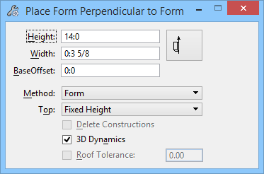
Specifies the height of the form, unless a shape or form above prohibits extrusion. If a shape above only partially blocks extrusion, Height controls the portion of the form that can be extruded past the overlying shape or form. Enabled when the option is selected. Note: Height extrusion direction is defined by either the Z-axis, perpendicular to the view; or, if AccuDraw is on, by the AccuDraw Z-axis.
|
| Width |
Specifies the width of the form. |
| Placement icon |
Controls the position of the form relative to the placement points which define the start and end points of the form:
 Places the form to the left of the creation line (baseline). Places the form to the left of the creation line (baseline).  Places the form centered on the creation line. Places the form centered on the creation line.  Places the form to the right of the creation line. Places the form to the right of the creation line.
|
| Method |
Controls what the new placed form is parallel to:
- Forms — The new linear form is placed between Building forms.
- 2 Imaginary Lines — The new linear form is placed between imaginary lines.
|
| Top |
Controls the geometry and location of the top of a form:
- Fixed Height — The form has a uniform height as specified in the Height field. The top face of the form is parallel to the bottom face.
- Connect Shapes — The form is extruded so that it connects to one or more shapes and/or forms. Selecting Connect Shapes displays the Delete Construction check box, which enables or disables the deletion of the limiting shapes and/or forms.
- Connect 3 pts — The top of the form is located in an imaginary plane defined by three data points.
- Connect 2 pts/View — The top of the form is located in an imaginary plane constructed through two data points and perpendicular to the view where the last data point is entered.
|
| Delete Constructions |
Enabled when the option is selected, limiting shapes and forms are deleted when on. |
| 3D Dynamics |
During placement, controls whether the display of the form being placed dynamically displays in 3D or in 2D: If on, forms being placed dynamically display in 3D.
If off, forms being placed display in 2D.
|
| Roof Tolerance |
Enabled when the option is selected, a curved connecting shape is stroked using the specified tolerance before it is used to create a roof on the form when on. The curved shape is used to create a feature on the form that is the exact shape of the curve when off. |
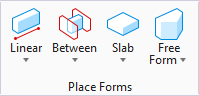
 Creates a form that is placed perpendicular to an existing form or an imaginary line.